The project of the house, first of all, will help you to imagine how your future house will look on the landscape. And floor sketches will help you understand what your future home will look like from the inside.
All our projects go through a full design cycle and are ready for . Blueprints high level and designed to work with professional builders.
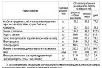
As part of our projects, we do not provide estimates. We do this consciously, as prices change, depending on the specifics of the local market for materials and services, transport accessibility and building site. Even climatic conditions can affect prices. Therefore, we cannot provide exact prices. But you can calculate all the prices yourself, because the project gives a complete picture of the volume and quantity of material for construction.
TopDom company provides house projects, which include a complete set of drawings, consisting of three sections:
1. Architectural section
The architectural section consists of several parts.
- First, it is a list of drawings.
- Secondly, general data about the project and its specifications.
- Thirdly, there will be a floor plan that includes the layout of each floor of the house. Also in the floor plan you can see all interior spaces, find out their overall dimensions and area.
These drawings will indicate the location of all doors, windows, the location of ventilation shafts and fireplaces with chimneys, the thickness of walls and partitions, the height of the floor, relative to the zero mark. All dimensions are indicated along the axes of the corresponding walls.
- Fourth, architectural section consists of drawings of facades that show the frontal images of the house from each side. This will allow you to see the location of windows, garage doors, balconies, overhangs and roof ridges and their location in height, and other elements of the facade.
- Fifth, the architectural section includes drawings of the vertical, longitudinal and cross section of the house. These drawings are necessary for you so that you can easily determine the height of the premises on the floors, the angle of inclination of the roof slopes in the attic, the depth of the basement or basement floor.

2. Structural section
The structural section consists of
- general data,
- layouts of foundation elements, stairs, ceilings, truss structures,
- detailed drawings of individual units,
- product and material specifications.
We draw your attention to the drawings of installation plans, which are also included in this section.
These drawings will allow you to get acquainted element by element with the design of the foundation, ceilings, truss system, floors, etc. Here, the layout of concrete blocks of foundations, beams and floor slabs, sections of monolithic concreting with reinforcement elements, etc. will be indicated.
As for the most complex junctions of structural elements to each other and parts, they are shown separately in the drawings. Here you will find the main dimensions and bindings along the axes.

3. Engineering section
The engineering section consists of
- schemes of water supply and sewerage systems (VK),
- general explanation about calculations,
- heating and ventilation (HV) schemes,
- electrical equipment (EO),
- specifications of equipment, products and materials.
The documents also spelled out diagrams of the life support system, which include floor plans. On each floor, we indicate the passage of distribution pipelines for cold and hot water supply, as well as pipes with domestic sewage and heating pipes.
The implemented project of a private house from the architectural bureau TopDom
Architectural plan as part of the project
The architectural plan is integral part project.
Definition 1
An architectural project is an architectural part of construction and urban planning documentation, which contains architectural solutions to the extent necessary for the development of documentation for construction projects.
In the design of building structures, as a rule, the participation of an architect is necessary, therefore such a plan is called an architectural plan. The architectural solutions of the structure must take into account such requirements for the object as:
- social;
- functional;
- engineering;
- fire fighting;
- architectural and artistic.
Depending on the purpose of the drawing, floor plans, basement, attic, roofing are distinguished. There are installation plans, which are layouts of elements of prefabricated structures (foundations, ceilings, frames, etc.). In the names located on the construction drawings, it is customary to observe certain terminology, for example: “Plan at around 0.000”, “Plan 1-18 floors”, etc.
Structural elements that fall into the section (columns, walls, beams) are drawn on the plan with a solid main line. On the drawings of plans, coordination axes, chains of external and internal dimensions, including the thickness of walls and partitions, the area of \u200b\u200bthe premises, the level marks of the finished floor (in the case of different levels). On the building plan, the doors must be marked, the names of the premises (or their numbering), as well as the built-in sanitary equipment, must be indicated.
Figure 1. Architectural plan of the building. Author24 - online exchange of student papers
In demonstration drawings, floor plans should provide very comprehensive information about the compositional solution of the construction site. This should reflect the structure of the internal space and the connection of the premises. In this regard, demonstration drawings are not recommended to be overloaded with unnecessary information in the form of dimensions or markings of premises.
On the demonstration plans, the coordination axes are depicted and the main overall dimensions of the structure or room are plotted. The coordination axes here are not drawn along the entire length of the building with a dash-dotted line, as in the working drawings. To clarify the purpose of the premises in each of them, they write the corresponding name or serial number, which is subsequently entered in the explication table. On the plans of structures, it is imperative to mark the places of sections and cuts, as well as give a link to them.
Remark 1
I must say that the degree of saturation of the plan depends on the scale that is chosen in a given situation. The larger the scale is chosen, the more attention it requires to the details of the structure.
Construction documentation
In accordance with the Town Planning Code, architectural and construction design is carried out through the preparation design and estimate documentation. These documents are being developed for capital construction and its parts, as well as buildings under construction and reconstruction. AT town planning code all sections are also listed project documentation relating to capital construction projects. Among them:
- explanatory note;
- scheme of the planning organization of the land plot;
- architectural solutions;
- construction organization project, etc.
Varieties of architectural plans
An architectural plan is one of the three main types of architectural drawings, which are two-dimensional projections of three-dimensional structures. The other two are the section and the facade of the building. In all three cases, the observer's gaze is perpendicular to the projection plane, on which the elements and surfaces of structures are depicted.
In general, when talking about a plan, they mean that the given plane is horizontal, parallel to the floor or ground. At its core, the plan is nothing more than a view of the building from above, in cross section, which is made at an imaginary level above the line of window sills.
The most common type of architectural plan is the floor plan. It reflects the rooms located on the same floor, as well as their size, shape and connection with each other. Also on the plan are windows, doors and other important objects, up to radiators, and sometimes pieces of furniture.
One of the conditions for drawing architectural plans is to maintain scale. This condition will allow a specialist to judge the proportions of the arrangement of certain structural elements relative to each other, as well as to evaluate their parameters with the necessary accuracy.
The plan was used by many famous architects, such as Frank Lloyd Wright, as a stimulus for the development of underlying logic. The management of spaces, constructions, scales and textures is based on these principles. For example, a rectangular grid on a building plan might mean that the structure's floor will be concrete.
floor plans allow to display all alternative designs of architects. Software, based on the CAD base, helps modern specialists to visualize any creative fantasies in a short time.
I must say that the working sketches and working plans of architects can seem very confusing. They are created for the initial assessment of the cost of the project, bidding and demonstration to customers. The architectural plan can be supplied with many callouts of an explanatory nature, as well as links to other drawings, notes and marks. All this information relates to the intended material of supporting structures, doors and other components.
The general plan of the site is formed according to the same rules as the floor plan. The difference lies in the fact that it depicts the building, taking into account its intended orientation on the existing site. On the master plan there is information about the interaction of the building with external objects, such as roads, trees, water bodies, etc. Currently, in practice, there is a combined version, which is a floor plan integrated into the surrounding landscape.
The project of a house is a document of control over the architectural and construction quality, as well as the consumption of constructive and finishing materials. Having decided to build without a project, you will not have accurate information about what and how it should be, you will not be able to control the consumption of materials and funds. The consequences may be different: the foundations may not withstand the loads or there will be no stairs to the second floor.
However, the consequence of construction without a project is not only low architectural and construction quality and illiquidity finished house, but also the impossibility of legal construction, and as a result, the impossibility of registering a house as a property. You will need a copy of the project documentation already when applying for a building permit.
The project of the house includes two main parts:
1. architectural and construction
This section contains architectural and construction drawings, which indicate the accuracy characteristics of the geometric parameters of buildings, structures, structures and their elements.
Floor plans - they show the placement of individual rooms and their dimensions, areas, placement of walls, door and window openings, kitchen and sanitary facilities, equipment;
Roof truss plan - it shows the system of roof structural elements and their sections;
Specification of the elements of the roof truss structure - a list of the range and quantity;
Roof plan - it shows its shape, dimensions, angle of inclination of the roof slope, as well as the placement of dormer windows, lucarnes, skylights and ventilation pipes;
Sections of the house - they show all the elements of the building after crossing it along or across from the roof to the foundations, i.e. sections of the floor, ceilings, roofs;
Facades of the house - they show appearance houses from the main entrance, behind and on the side;
Specification of elements of door and window joinery - a list of windows and doors in the project and how to open them;
Structural section
This section provides general data, layouts of elements of foundations, ceilings, stairs, truss structures, detailed drawings of individual units, specifications of products and materials.
Cross section of foundations - it shows the dimensions strip foundations, the depth of their base, the materials used for their manufacture;
Calculations for static and strength.
The architectural and construction part should include not only facades, but also detailed drawings with dimensions and material parameters. In the case of medium and large lightning hazard, it is necessary to make a lightning protection installation, that is, it is additionally added lightning rod section.
2. engineering.
Engineering documentation in most cases has three sections:
- "Plumbing and sewerage",
- "Heating and ventilation"
- "Electrics".
In addition, the architectural passport of the project must be attached to the project:
Part architectural passport includes:
Copy of the license of the author of the project, explanatory note, colored facades, facades along the axes, floor plans, sections along the axes, roof plan.
An architectural design is a preparatory construction plan that must be strictly adhered to in order to achieve the desired result. Both the reliability of the structure and the labor costs for construction depend on how competently it is drawn up, therefore, only professionals should trust the creation of the project.
The architectural workshop of Ivan Yuryma has vast experience in creating projects. But before ordering a plan, you might want to know what it is.
Stages of creating an architectural project
It is very difficult to draft structures, so the entire design process is divided into four stages:
- 1. Preparatory stage - first, all the information necessary for construction is collected and analyzed, including regulatory documentation and literature. At the same time, a preliminary work plan is outlined in order to calculate the approximate financial costs.
- 2. The draft stage is the creation of several sketches at once, reflecting the design and style of the future building, from which the customer then chooses the most suitable one. This takes into account the dimensions of the future structure and the relief of the site, as well as the requirements for architecture, aesthetics and functionality of the structure.
- 3. Development of documentation is the stage of paperwork, which begins after agreement with the customer on the features of the preliminary design and its approval.
- 4. Development of the future interior is the final stage of design, which includes the solution of issues on the design and style of the future building.
It is worth considering that according to the documentation compiled by the company at the third stage of design, one can judge its professionalism.

Project documentation
A well-designed project consists of:
- 1. Architectural documentation, which indicates how the building will be located and look. This, in fact, is an image of the future structure on which further calculations are made.
- 2. Design documentation, which includes plans for the constituent parts of the building (foundation, floors, roofs, etc.), its appearance in section. It is also noted how much materials will be needed for construction.
- 3. Engineering and technological documentation, which displays all communications of the building, as well as the features of their connection.
- 4. Estimate documentation, reflecting the entire material part of the construction (the cost of materials and work).
As you can see, an architectural project is a complex, but very important stage of construction.
Why do we need an architectural project, the video tells:
Full individual project ours consists of:
- Draft design (ER)
- Working draft (AR, KR)
- engineering project(OV + EO + VK)
- The passport
ATTENTION! For many firms, “full project” means a working project (AR + KR), be careful not to fall for the bait!
Sketch design and why is it needed?
At first glance, it may seem that a preliminary design is something superfluous, because all the information about the construction is already in the Working Draft, the question arises - why spend money on a sketch? The answer is simple: the preliminary design stage is the base, the foundation from which they start in all directions, from the initial layout to the stage of engineering and geological survey.
A draft design is a set of drawings and pictures, with the help of which a complete picture of the final result of construction is obtained. At the stage of preliminary design, comprehensive work is carried out on the concept of the future home. The architect has an idea about the wishes of the customer, and based on them, further work is carried out. There are several stages of preliminary design.
The location of the house on the site
At this stage, the house is oriented to the cardinal points and located relative to neighboring plots, roads, terrain, trees. It is calculated from which side it will be more rational to bring communications. At the same time, fire and sanitary safety standards must be observed. In addition, the complex layout of the site as a whole is also being considered. The architect calculates the location of additional buildings, based on the wishes of the client - a garage, a bathhouse, a gazebo, outbuildings.

Floor plans
Perhaps one of key points future comfortable life in the house - planning.Based on your wishes, the architect will develop an optimal layout of all rooms. If the architect considers your preferences not rational from a financial point of view, you will be offered alternative options that are as close as possible to your wishes, but with significant savings during construction. After all, an extra 40 centimeters on a draft design can turn into a tidy sum during construction!
Facades and appearance

This is, in fact, the look of your future home. The location and dimensions of windows, doors, balconies, terraces, floor heights, roofing - all this will be taken into account at the draft design stage. At this stage, you can still experiment, for example, move the windows, resize them and calculate whether there will be enough light in the room from three windows on the east side or whether it is worth adding another one from the south. It remains for the architect to model the 3D image of the house and the site in color.

As a result, you will have a folder with a Sketch solution containing:
- common data
- Explanatory note
- floor plans
- Roofing design
- Two cuts
- Link to the site
- 3D visualization
We hope you figured out the process of preliminary design. If you have additional questions - call us, we will definitely answer and advise.
working draft
As we have already found out, the working draft consists of Architectural Solution(AR) and Constructive Solution (CR). Let's take a closer look at what it is. We start from the preliminary design and move on. 
architectural solution is a comprehensive addition and specific refinement of the sketch. In the architectural solution, it is precisely the architectural part that is described in detail. The architectural solution is included in the project documentation as a mandatory section, in accordance with the Government Decree Russian Federation dated February 16, 2008 No. 87. The architectural design takes into account the requirements of urban planning legislation, state standards in the field of design and construction. This is a binding document for both parties to the implementation of an architectural project.
As a result of creating an architectural solution, you will have a folder with documents:
- common data
- Explanatory note
- floor plans
- Roofing design
- Four facades + color solution
- Two cuts
- General plan
- Marking plans
- Filling specifications for window and door openings
- Smoke ventilation ducts and drainage system (assemblies, specifications)
- Room finishing list
- Explication of the floors
Design Solution (CR)- part of the project of the house, aimed at the implementation of architectural ideas. KR determines the purpose of structures that ensure the strength, stability and durability of the entire house. According to the Decree of the Government of the Russian Federation of February 16, 2008 No. 87, in addition to the Architectural Solution, the design documentation also necessarily includes the section "Constructive and space-planning solutions" with a text and graphic part.
Design documentation:
- Foundation plan (indicates the exact location of the foundation, its dimensions, the depth of the foundation; specifications, design loads, main nodes are given)
- Lintel plan (these drawings show the layout of the lintels and purlins, as well as their dimensions, and provide the relevant specifications)
- Floor plan (floor layout, placement and installation of beams is being carried out; the necessary components and technical instructions are attached)
- Plan of the truss system (these drawings include: a diagram of the roof structural elements of their section, wood specifications, nodes and sections, technical instructions for the installation of truss structures and coatings)
- Roof plan (shown the shape, dimensions of the roof, the slope of all its planes, as well as the placement of skylights, chimneys and pipes)
- Sections (all characteristic elements of the building structure are indicated that appear when it is cut along or across from the roof to the foundation, i.e. the levels of the floor, floors, roofs, as well as ways to solve some of the connections of the building elements, for example, walls with ceilings, walls with roofs )
- Facades (the exact main, courtyard and side views are shown, as well as a description of the finishing materials and thermal insulation of the outer walls of the building, diagrams are drawn constructive solution thermal insulation)
- Specification for wall materials
- Consumption of masonry materials
- All drawings of the constructive solution are supplemented with technical instructions and recommendations for the implementation of construction and installation works.
engineering project
Engineering support buildings is an important task in the design. It is at this stage that the calculation of all mandatory systems life support.